In barrel distortion, the image seems bloated in the middle and pinched at the sides.
 The opposite happens for pin cushion distortion.
 In this activity, we will try to correct pin cushion and barrel distortions.
First we need an image of a regularly repeating pattern like a grid or checkerboard as reference.
This will help us visualize the distortion that happens across the image.
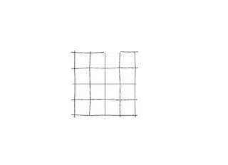
Below, we show such a pattern for the barrel distortion

and for the pincushion distortion

Now, what we need to find is the transformation that will map the distorted image to the ideal image.

First we look at the transformation of pixel coordinates.

We assume that the coordinates are transformed in both directions simultaneously, so that r and s would be bilinear functions
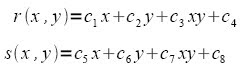 The distorted coordinates would therefore be given by
 To find the eight unknown coefficients c1-c8, we use the 4 vertices of a grid. These coefficients are valid only for points within the gird used and must therefore be generated for each grid in the image.
Using the four vertices, and rewriting the eight equations in matrix form we have
 The distorted coordinates are easy to find. In Scilab, we just use the locate() function.
For the barrel distortion image above, the located points are marked with red crosses

Similarly for the pincushion
 The ideal coordinates on the other hand are generated from the grid length down and across a grid from the most undistorted portion of the image (optical axis of the camera). In my program, I used
////count number of pixels down and across one box
//// choose diagonal points (origin and 1,1)
scf(1); clf();
imshow(im);
xy=locate(2,1);
//// ideal vertices
xoyo=xy(:,1);
xideal=(xoyo(1) + [-cols/2:cols/2]*xratio);
yideal=sort(xoyo(2) + [-rows/2:rows/2]*yratio);
a=ones(1:cols+3);
b=ones(1:rows+3);
xi=a'*xideal;
yi=yideal'*b;
where xi and yi are matrices that contain the column and row values of the grid vertices respectively. For example xi(1,2) will give the column value of the vertex at topmost row and 2nd to the left column.
We now know both the ideal and distorted vertices.
For the succeeding parts, I will place my discussions inside the code using comments.
(Its rather hard to discuss it step by step since they are all inside common loops)
/// The 2 for loops go through each grid
for i=1:rows
for j=1:cols
///Now to compute the 8 coefficients for each grid, I made the following code.
//// Computation of Coefficients per grid
T=[xi(i,j) yi(i,j) xi(i,j)*yi(i,j) 1; xi(i+1,j) yi(i+1,j) xi(i+1,j)*yi(i+1,j) 1; xi(i+1,j+1) yi(i+1,j+1)xi(i+1,j+1)*yi(i+1,j+1) 1; xi(i,j+1) yi(i,j+1) xi(i,j+1)*yi(i,j+1) 1];
Xd=([xd(i,j) xd(i+1,j) xd(i+1,j+1) xd(i,j+1)])';
Yd=([yd(i,j) yd(i+1,j) yd(i+1,j+1) yd(i,j+1)])';
C1_4=inv(T)*Xd;
C5_8=inv(T)*Yd;
c=[C1_4;C5_8];
//// The vertices of the ideal grid are given by
Xi=([xi(i,j) xi(i+1,j) xi(i+1,j+1) xi(i,j+1)])';
Yi=([yi(i,j) yi(i+1,j) yi(i+1,j+1) yi(i,j+1)])';
xir=floor(Xi); yir=floor(Yi);
//Now we go through each pixel in the grid.
for l=min(yir):max(yir)-1
for m=min(xir):max(xir)-1
//Per pixel in the ideal grid the location of that point in the distorted image is given by
xdistort2=c(1)*m + c(2)*l + c(3)*m.*l + c(4);
ydistort2=c(5)*m + c(6)*l + c(7)*m.*l + c(8);
xdr2=floor(xdistort2);
ydr2=floor(ydistort2);
////// Gray Level Interpolation
// ////The final part of the problem is to find the gray level value at the ideal pixel location.
//////This should just be a matter of assigning to the ideal coordinates the pixel value at the corresponding //////distorted coordinates (calculated using the two equations above).
//////However, the two equations above would not give exact integers all the time and so we need to //////interpolate the graylevel value. The interpolation that will be done here is the bilinear interpolation, //////whereas the gray level value at (x,y) is given by

////// a b c d can be obtained from the four nearest pixels of the location rather like the way we calculated the //////unknown coefficients c1-c4.
V=[im(ydr2,xdr2); im(ydr2+1,xdr2); im(ydr2,xdr2+1); im(ydr2+1,xdr2+1)];
Tv=[xdr2 ydr2 xdr2*ydr2 1; xdr2 (ydr2+1) xdr2*(ydr2+1) 1; (xdr2+1) ydr2 (xdr2+1)*ydr2 1; (xdr2 +1) (ydr2 +1) (xdr2 +1)*(ydr2+1) 1];
abcd=inv(Tv)*V;
im2(l,m)=(abcd(1)*xdistort2 +abcd(2)*ydistort2 + abcd(3)*xdistort2.*ydistort2 + abcd(4));
end
end
end
end
After correction the barrel distorted image now looks like (only the center 4 rows and columns)
 while the pin cushion image looks like (only the center 4 rows and columns)

 The distorted coordinates would therefore be given by
 To find the eight unknown coefficients c1-c8, we use the 4 vertices of a grid. These coefficients are valid only for points within the gird used and must therefore be generated for each grid in the image.
Using the four vertices, and rewriting the eight equations in matrix form we have
 The distorted coordinates are easy to find. In Scilab, we just use the locate() function.
For the barrel distortion image above, the located points are marked with red crosses

Similarly for the pincushion
 The ideal coordinates on the other hand are generated from the grid length down and across a grid from the most undistorted portion of the image (optical axis of the camera). In my program, I used
////count number of pixels down and across one box
//// choose diagonal points (origin and 1,1)
scf(1); clf();
imshow(im);
xy=locate(2,1);
//// ideal vertices
xoyo=xy(:,1);
xideal=(xoyo(1) + [-cols/2:cols/2]*xratio);
yideal=sort(xoyo(2) + [-rows/2:rows/2]*yratio);
a=ones(1:cols+3);
b=ones(1:rows+3);
xi=a'*xideal;
yi=yideal'*b;
where xi and yi are matrices that contain the column and row values of the grid vertices respectively. For example xi(1,2) will give the column value of the vertex at topmost row and 2nd to the left column.
We now know both the ideal and distorted vertices.
For the succeeding parts, I will place my discussions inside the code using comments.
(Its rather hard to discuss it step by step since they are all inside common loops)
/// The 2 for loops go through each grid
for i=1:rows
for j=1:cols
///Now to compute the 8 coefficients for each grid, I made the following code.
//// Computation of Coefficients per grid
T=[xi(i,j) yi(i,j) xi(i,j)*yi(i,j) 1; xi(i+1,j) yi(i+1,j) xi(i+1,j)*yi(i+1,j) 1; xi(i+1,j+1) yi(i+1,j+1)xi(i+1,j+1)*yi(i+1,j+1) 1; xi(i,j+1) yi(i,j+1) xi(i,j+1)*yi(i,j+1) 1];
Xd=([xd(i,j) xd(i+1,j) xd(i+1,j+1) xd(i,j+1)])';
Yd=([yd(i,j) yd(i+1,j) yd(i+1,j+1) yd(i,j+1)])';
C1_4=inv(T)*Xd;
C5_8=inv(T)*Yd;
c=[C1_4;C5_8];
//// The vertices of the ideal grid are given by
Xi=([xi(i,j) xi(i+1,j) xi(i+1,j+1) xi(i,j+1)])';
Yi=([yi(i,j) yi(i+1,j) yi(i+1,j+1) yi(i,j+1)])';
xir=floor(Xi); yir=floor(Yi);
//Now we go through each pixel in the grid.
for l=min(yir):max(yir)-1
for m=min(xir):max(xir)-1
//Per pixel in the ideal grid the location of that point in the distorted image is given by
xdistort2=c(1)*m + c(2)*l + c(3)*m.*l + c(4);
ydistort2=c(5)*m + c(6)*l + c(7)*m.*l + c(8);
xdr2=floor(xdistort2);
ydr2=floor(ydistort2);
////// Gray Level Interpolation
// ////The final part of the problem is to find the gray level value at the ideal pixel location.
//////This should just be a matter of assigning to the ideal coordinates the pixel value at the corresponding //////distorted coordinates (calculated using the two equations above).
//////However, the two equations above would not give exact integers all the time and so we need to //////interpolate the graylevel value. The interpolation that will be done here is the bilinear interpolation, //////whereas the gray level value at (x,y) is given by

V=[im(ydr2,xdr2); im(ydr2+1,xdr2); im(ydr2,xdr2+1); im(ydr2+1,xdr2+1)];
Tv=[xdr2 ydr2 xdr2*ydr2 1; xdr2 (ydr2+1) xdr2*(ydr2+1) 1; (xdr2+1) ydr2 (xdr2+1)*ydr2 1; (xdr2 +1) (ydr2 +1) (xdr2 +1)*(ydr2+1) 1];
abcd=inv(Tv)*V;
im2(l,m)=(abcd(1)*xdistort2 +abcd(2)*ydistort2 + abcd(3)*xdistort2.*ydistort2 + abcd(4));
end
end
end
end
After correction the barrel distorted image now looks like (only the center 4 rows and columns)


I also tried correcting distortions on more complicated images, like the cd rack below

and here is the result

Alternately, undistorted images can be distorted using the same procedure. We just have to superimpose a distorted pattern over an undistorted image, apply correction to the lines and voila! The image becomes distorted.
For this activity, I give myself a grade of 10. I was able to implement the correction for the barrel and pincushion distortion.
Images from
http://www.astrosurf.com/buil/iris/tutorial19
Ref
Activity 13 Manual
No comments:
Post a Comment